

Copper Nickel Blind Flange
HC manufactures copper nickel blind flanges for marine, offshore and seawater piping systems. Available in CuNi 90/10 (UNS C70600) and CuNi 70/30 (UNS C71500), our blind flanges can be supplied to ASME B16.5 Class 150 and Class 300 requirements, with raised face and flat face options.

- Size
- NPS 1/2–24
- Pressure Class
- Class 150 · Class 300
- Flange Face
- Flat Face (FF) · Raised Face (RF)
What Is a Copper Nickel Blind Flange?
A copper nickel blind flange is a solid flange without a center bore. It is bolted to a mating flange to close the end of a copper nickel pipeline, valve opening, nozzle or reserved branch connection.
Unlike a flange used to pass fluid through the bore, a blind flange provides a complete closure at the piping connection. Because it can be removed without cutting the pipe, it is often used where a line may need to be isolated, inspected, maintained or extended later.
For seawater and marine systems, the flange material is selected to provide suitable corrosion resistance together with the mechanical and dimensional properties required by the piping design. HC supplies blind flanges in CuNi 90/10 and CuNi 70/30, with dimensions, pressure class and facing selected according to the applicable standard and project specification.
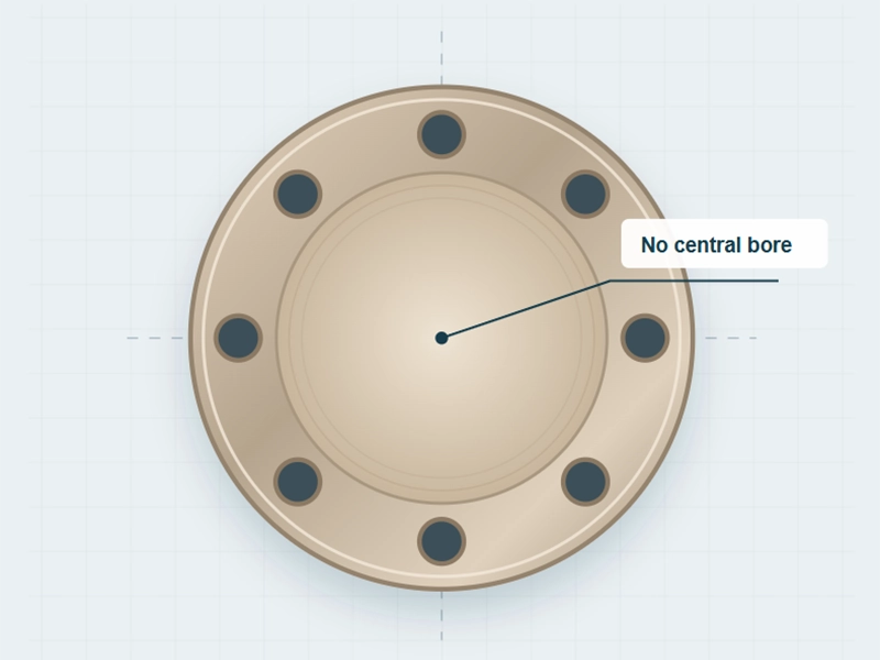
Copper Nickel Blind Flange Specifications
| Material Specification | ASTM B151 · UNS C70600 · CuNi10Fe1.6Mn · 7060X |
| Dimensional Standard | ASME B16.5 |
| Available Standards | EEMUA · DIN · JIS · ANSI · ASME · BS · EN |
| Nominal Size | 1/2" to 24" |
| Pressure Class | Class 150 · Class 300 |
| Flange Face | Flat Face (FF) · Raised Face (RF) |
| Material Grades | Copper Nickel 90/10 (C70600) · Copper Nickel 70/30 (C71500) |
| MOQ | Available on request |
| Packaging | Export packing according to order requirements |
Copper Nickel Blind Flange Material Options
HC supplies copper nickel blind flanges in CuNi 90/10 (UNS C70600) and CuNi 70/30 (UNS C71500). The two grades are both used for marine and seawater piping, but the specified alloy should match the piping material, service conditions and project standard rather than being selected only by nickel content. For a wider range of connection types, see our copper nickel flanges.
CuNi 90/10 — UNS C70600
CuNi 90/10 is a common copper nickel material for seawater and marine piping. It is frequently specified for shipboard cooling lines, seawater services and general offshore piping.
- Material: CuNi 90/10 / UNS C70600
- Common service: seawater, cooling water and marine piping
- Flange use: blind, slip-on, weld neck and other configurations
- Suitable dimensions and pressure class are determined by the applicable flange standard
For the grade-specific product range, see 90/10 copper nickel flanges .
CuNi 70/30 — UNS C71500
CuNi 70/30 contains a higher proportion of nickel and is specified for marine and seawater systems where the project requires the C71500 alloy. Its use is common in offshore, shipbuilding and other demanding seawater-service piping.
- Material: CuNi 70/30 / UNS C71500
- Common service: seawater and marine piping
- Typical use: offshore, desalination and marine equipment piping
- Final material, dimensions and pressure class should follow the project specification
See our 70/30 copper nickel flanges for additional C71500 flange information.
C70600 and C71500 should not be treated as automatic substitutes. Material selection should take into account seawater quality, flow conditions, temperature, piping design, galvanic contact with dissimilar metals and the requirements of the applicable standard or project specification. The blind flange should also match the connected pipe material, flange dimensions, facing and pressure class.
C70600 vs C71500 Copper Nickel Blind Flange Materials
C70600 and C71500 are both copper-nickel alloys used for marine and seawater piping. The two grades have different nickel contents and material properties, so the flange material should be matched to the piping specification and service conditions rather than treated as interchangeable.
- Alloy grades: CuNi 90/10 (C70600) is commonly specified for seawater cooling systems, ship piping and general marine service, while CuNi 70/30 (C71500) is used where the higher-nickel grade and its specified mechanical and service properties are required.
- Mechanical requirements: The required strength and other mechanical properties should be checked against the applicable material standard and product form. A higher nickel content alone is not a sufficient reason to change grades.
- Service conditions: Seawater temperature, flow conditions, pressure, piping design and the intended service should be considered when selecting the blind flange material.
- Project specification: The flange grade should correspond with the specified pipe, fittings and applicable standards. C70600 is not automatically a substitute for C71500, and C71500 should not be selected simply because it contains more nickel.
Material selection should follow the engineering specification. Check the alloy designation, applicable material standard, pressure class, mechanical requirements and service conditions before substituting C70600 or C71500.
C70600 vs C71500 Copper Nickel Blind Flange Chemical Composition
90/10 (UNS C70600) Copper Nickel Flanges Chemical Composition
| KME CuNi90/10 | DIN 17664 2.0882 | BS 2871 CN102 | ASTM B466 C70600 | JIS H3300 C7060T | DIN 86019 2.1972 | EEMUA 234 UNS 7060X | GB/T 5231 BFe10-1.6-1 | |
| Ni% | 10.0-11.0 | 9.0-11.0 | 10.0-11.0 | 9.0-11.0 | 9.0-11.0 | 9.0-11.0 | 10.0-11.0 | 9.0-11.0 |
| Fe% | 1.5-1.8 | 1.0-2.0 | 1.0-2.0 | 1.0-1.8 | 1.0-1.8 | 1.5-1.8 | 1.5-2.0 | 1.5-1.8 |
| Mn% | 0.6-1.0 | 0.5-1.0 | 0.5-1.0 | max.1.0 | 0.2-1.0 | 0.5-1.0 | 0.5-1.0 | 0.5-1.0 |
| C% | max.0.05 | max.0.05 | max.0.05 | max.0.05 | max.0.05 | max.0.05 | max.0.05 | |
| Pb% | max.0.01 | max.0.03 | max.0.01 | max.0.02 | max.0.05 | max.0.01 | max.0.01 | max.0.03 |
| S% | max.0.005 | max.0.02 | max.0.05 | max.0.02 | max.0.005 | max.0.02 | max.0.01 | |
| P% | max.0.02 | max.0.02 | max.0.02 | max.0.02 | max.0.02 | max.0.02 | ||
| Zn% | max.0.05 | max.0.50 | max.0.50 | max.0.50 | max.0.05 | max.0.20 | max.0.20 | |
| Other | max.0.20 | max.0.30 | max.0.20 | max.0.30 | max.0.40 | |||
| Cu% | rem. | rem. | rem. | rem. | +Ni+Fe+Mn min99.5 | rem. | rem. | rem. |
70/30 (UNS C71500) Copper Nickel Flanges Chemical Composition
| KME CuNi70/30 | DIN 176642.0882 | BS 2871 CN107 | ASTM B466C71500 | JIS H3300C7150T | |
| Ni% | 30.0-32.0 | 30.0-32.0 | 30.0-32.0 | 29.0-33.0 | 29.0-33.0 |
| Fe% | 0.47-0.7 | 0.4-1.0 | 0.4-1.0 | 0.4-1.0 | 0.4-1.0 |
| Mn% | 0.5-1.0 | 0.5-1.5 | 0.5-1.5 | max.1.0 | 0.2-1.0 |
| C% | max.0.04 | max.0.05 | max.0.06 | max.0.05 | |
| Pb% | max.0.01 | max.0.03 | max.0.01 | max.0.02 | max.0.05 |
| S% | max.0.01 | max.0.02 | max.0.08 | max.0.02 | |
| P% | max.0.02 | max.0.02 | max.0.02 | ||
| Zn% | max.0.20 | max.0.50 | max.0.50 | max.0.50 | |
| Other | max.0.30 | max.0.30 | |||
| Cu% | rem. | rem. | rem. | rem. | +Ni+Fe+Mn min99.5 |
RF vs FF Copper Nickel Blind Flange
RF and FF blind flanges differ mainly in the shape of the flange face where the gasket is installed. A raised face (RF) flange has a defined raised sealing surface, while a flat face (FF) flange keeps the entire face at the same level. The choice should follow the mating flange, gasket arrangement and applicable piping specification.
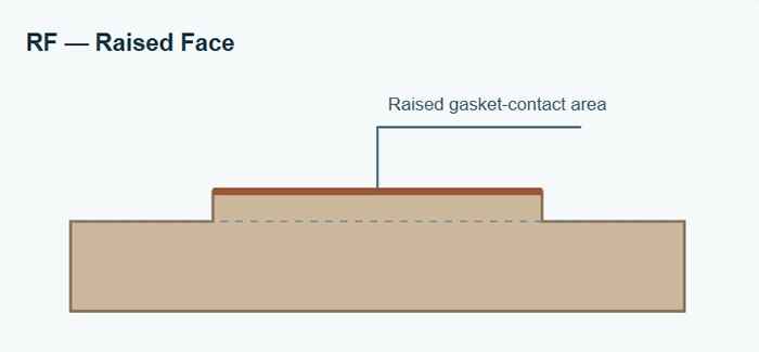
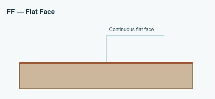
For copper nickel blind flange assemblies, RF and FF should not be treated as interchangeable details.
| Comparison | Raised Face — RF | Flat Face — FF |
| Face geometry | An elevated gasket-contact area around the centre of the flange | A continuous flat face without a raised sealing area |
| Typical gasket arrangement | A gasket located within the bolt circle and sized for the raised face | Often a full-face gasket extending around the bolt holes |
| Bolt-load behaviour | Concentrates gasket load over a smaller sealing area | With a full-face gasket, distributes contact over a broader area |
| Typical selection basis | A piping specification calling for an RF connection | Equipment or piping specified for an FF connection |
| Main compatibility check | Raised-face dimensions, gasket type and required surface finish | Mating flange material, gasket arrangement and permitted bolt load |
Copper Nickel Blind Flange Size Chart
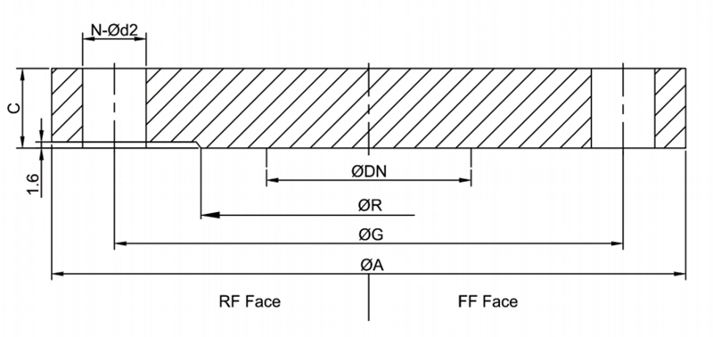
ASME B16.5 CL 150 Copper Nickel Blind Flange Size Chart
| specification | DN | A | C | R | G | N-Od2 | Weight |
| inch | mm | mm | mm | mm | mm | kg | |
| 1/2" | 15 | 88.9 | 11.2 | 34.9 | 60.3 | 4-15.9 | 0.90 |
| 3/4" | 20 | 98.4 | 12.7 | 42.9 | 69.8 | 4-15.9 | 1.05 |
| 1" | 25 | 107.9 | 14.3 | 50.8 | 79.4 | 4-15.9 | 1.15 |
| 11/4" | 32 | 117.5 | 15.9 | 63.5 | 88.9 | 4-15.9 | 1.50 |
| 11/2" | 40 | 127 | 17.5 | 73 | 98.4 | 4-15.9 | 1.60 |
| 2" | 50 | 152.4 | 19.1 | 92.1 | 120.6 | 4-19 | 3.05 |
| 21/2" | 65 | 177.8 | 22.2 | 104.8 | 139.7 | 4-19 | 4.7 |
| 3" | 80 | 190.5 | 23.8 | 127 | 152.4 | 4-19 | 5.80 |
| 4" | 100 | 228.6 | 23.8 | 157.2 | 190.5 | 8-19 | 9.10 |
| 5" | 125 | 254 | 23.8 | 185.7 | 215.9 | 8-22.2 | 10.25 |
| 6" | 150 | 279.4 | 25.4 | 215.9 | 241.3 | 8-22.2 | 13.70 |
| 8" | 200 | 342.9 | 28.6 | 269.9 | 298.4 | 8-22.2 | 22.80 |
| 10" | 250 | 406.4 | 30.2 | 323.8 | 361.9 | 12-25.4 | 36.45 |
| 12" | 300 | 482.6 | 31.8 | 381 | 431.8 | 12-25.4 | 57.00 |
| 14" | 350 | 533.4 | 34.9 | 412.8 | 476.2 | 12-28.6 | 67.25 |
| 16" | 400 | 596.9 | 36.5 | 469.9 | 539.7 | 16-28.6 | 87.80 |
| 18" | 450 | 635 | 39.7 | 533.4 | 577.8 | 16-31.7 | 108.30 |
| 20" | 500 | 698.5 | 42.9 | 584.2 | 635 | 20-31.7 | 140.25 |
| 24" | 600 | 812.8 | 47.6 | 692.1 | 749.3 | 20-34.9 | 212.05 |
ASME B16.5 CL 300 Copper Nickel Blind Flange Size Chart
| specification | DN | A | C | R | G | N-Od2 | Weight |
| inch | mm | mm | mm | mm | mm | kg | |
| 1/2" | 15 | 95.2 | 14.3 | 34.9 | 66.7 | 4-15.9 | 1.15 |
| 3/4" | 20 | 117.5 | 15.9 | 42.9 | 82.5 | 4-19 | 1.70 |
| 1" | 25 | 123.8 | 17.5 | 50.8 | 88.9 | 4-19 | 2.30 |
| 11/4" | 32 | 133.3 | 19 | 63.5 | 98.4 | 4-19 | 2.85 |
| 11/2" | 40 | 155.6 | 20.6 | 73 | 114.3 | 4-22.2 | 3.40 |
| 2" | 50 | 165.1 | 22.2 | 92.1 | 127 | 8-19 | 4.00 |
| 21/2" | 65 | 190.5 | 25.4 | 104.8 | 149.2 | 8-22.2 | 6.30 |
| 3" | 80 | 209.5 | 28.6 | 127 | 168.3 | 8-22.2 | 8.00 |
| 4" | 100 | 254 | 31.8 | 157.2 | 200 | 8-22.2 | 13.70 |
| 5" | 125 | 279.4 | 34.9 | 185.7 | 234.9 | 8-22.2 | 18.25 |
| 6" | 150 | 317.5 | 36.5 | 215.9 | 269.9 | 12-22.2 | 26.20 |
| 8" | 200 | 381 | 41.3 | 269.9 | 330.2 | 12-25.4 | 41.60 |
| 10" | 250 | 444.5 | 47.6 | 323.8 | 387.3 | 16-28.6 | 65.55 |
| 12" | 300 | 520.7 | 50.8 | 381 | 450.8 | 16-31.7 | 94.60 |
| 14" | 350 | 584.2 | 54 | 412.8 | 514.3 | 20-31.7 | 122.0 |
| 16" | 400 | 647.7 | 57.2 | 469.9 | 571.5 | 20-34.9 | 158.45 |
| 18" | 450 | 711.2 | 60.3 | 533.4 | 628.6 | 24-34.9 | 201.80 |
| 20" | 500 | 774.7 | 63.5 | 584.2 | 685.8 | 24-34.9 | 254.20 |
| 24" | 600 | 914.4 | 69.8 | 692.1 | 812.8 | 24-41.3 | 389.90 |
Applications of Copper Nickel Blind Flanges
The application of a blind flange is not limited to simply "closing a pipe." In operating piping systems, it provides a removable closure point for isolation, maintenance, inspection, temporary shutdowns or future connections.
- Marine seawater cooling Closing spare branches, maintenance openings and unused equipment connections.
- Shipbuilding Blanking piping ends where the specified CuNi alloy must be maintained.
- Offshore installations Isolating branches or equipment nozzles in approved seawater utility systems.
- Desalination facilities Closing connections in seawater handling sections, subject to the process specification.
- Industrial cooling-water systems Providing removable end closures where water chemistry supports the use of copper nickel.
For other connection types in the same piping system, view our copper nickel flange range .
Copper Nickel Blind Flanges Quality Control
Copper nickel blind flange quality depends on both the material and the finished flange geometry. HC can arrange inspection according to the order specification and agreed inspection requirements.
Common Inspection Items
- Material verification
- Dimensional inspection
- Flange thickness inspection
- Bolt-hole inspection
- Sealing-face inspection
- Visual inspection
- Marking inspection
- Packing inspection
Request a Quote for Copper Nickel Blind Flanges
Send HC Aluminum your specifications for copper nickel blind flanges, including C70600 Cu-Ni 90/10 or C71500 Cu-Ni 70/30 material, flange standard, size, pressure class, face type and any drawing-based requirements. We can review your requirements and provide a quotation based on the specified flange dimensions and material.
Contact HC AluminumCopper Nickel Flanges and Related Piping Products
A copper nickel blind flange is typically used together with other piping components rather than as a standalone part. The flange, pipe, fittings, gasket and bolting should be checked against the same connection standard and service requirements before assembly.
HC supplies copper nickel flanges and matching piping components for marine, seawater and industrial piping applications, including standard and drawing-based requirements.
- Copper Nickel Flanges Standard copper nickel flange options for different piping connections.
- Copper Nickel Weld Neck Flanges Designed for welded pipe connections with a tapered hub.
- Copper Nickel Socket Weld Flanges Compact flange connections for suitable small-bore piping.
- Copper Nickel Threaded Flanges Threaded flange connections for applications where welding is not preferred.
- Copper Nickel Pipe CuNi pipe for matching seawater and marine piping systems.
- Copper Nickel Pipe Fittings Elbows, tees, reducers and other fittings for complete CuNi piping assemblies.
Why Choose HC for Copper Nickel Blind Flanges?
Specified Copper Nickel Grades
HC supplies copper nickel blind flanges in commonly specified grades including C70600 CuNi 90/10 and C71500 CuNi 70/30. The flange material is matched to the piping specification rather than treated as a one-grade-fits-all option.
Careful Dimensional Checking
Flange size, pressure class, face type, bolt-hole layout and applicable dimensional standard are checked before production to ensure the blind flange is made to the required connection details.
Support for Custom Requirements
HC can review customer drawings and technical specifications for non-standard dimensions, drilling patterns and project-specific inspection or documentation requirements.
FAQ – Copper Nickel Blind Flanges
Is a copper nickel blind flange welded to the pipe?
Normally, no. A copper nickel blind flange is bolted to a mating flange with a gasket between the flange faces. The mating flange may be welded to the pipe, while the blind flange remains removable.
What is the difference between C70600 and C71500 blind flanges?
C70600 is a copper-nickel 90/10 alloy, while C71500 is a copper-nickel 70/30 alloy. Their alloy compositions and mechanical characteristics differ, so the flange material should be selected according to the engineering design and project specification.
Are Class 150 and Class 300 copper nickel blind flanges available?
HC can supply copper nickel blind flange configurations for ASME B16.5 Class 150 and Class 300 requirements, where applicable to the specified size, material, facing and project standard.
What is the difference between RF and FF copper nickel blind flanges?
RF means Raised Face and FF means Flat Face. The two configurations have different sealing geometries and gasket arrangements. The correct choice depends on the mating flange, gasket, pressure class and piping specification.
What sizes of copper nickel blind flanges are available?
The applicable ASME B16.5 size range is NPS 1/2 through NPS 24. The final available size, pressure class, facing and dimensional configuration should be confirmed according to the selected material and project requirements.
Can HC manufacture copper nickel blind flanges according to drawings?
Yes. HC can review customer drawings and technical specifications for non-standard dimensions or project-specific requirements before production. The final manufacturing scope should be confirmed from the approved drawing and purchase specification.
Are copper nickel blind flanges suitable for seawater piping?
Copper nickel alloys are widely used in marine and seawater-related piping because of their corrosion resistance. The final flange material, dimensions, pressure class and connection arrangement should be selected according to the actual seawater conditions and piping design.
The following copper nickel products may interest you

Further reading: Copper Nickel PipesCopper Nickel ElbowsCopper Nickel TeesCopper Nickel ReducerCopper Nickel Pipe CapCopper Nickel FlangesCopper Nickel Threaded Pipe Fittings